Dallas Cathedral - Dallas, TX
Project Details
Structural Engineer
Jaster-Quintanilla Dallas, LLP, Dallas
Architect
ArchiTexas, Dallas
Steel Fabricator
Bratton Steel Inc., Dallas, AISC member
Steel Detailer
Draftco, Inc., Garland, Texas, AISC member
General Contractor
Andres Construction Services, Dallas
Engineering Software
RISA-3D
Detailing Software
SteelCAD, AutoCAD
“Modern structural steel framing makes possible a steeple that was envisioned more than 100 years ago.”
Project Summary
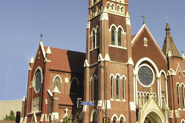
The tower of the cathedral shrine of the Virgin of Guadalupe in Dallas was designed in the late 1890’s as a 220′ structure with an ornate, european-style steeple.
One hundred years later, that design had never been realized—the tower had topped out at 85’ and the steeple was never constructed.
To celebrate the cathedral’s centennial year, the Catholic Diocese of Dallas undertook a $4.7 million, nine-month renovation of the tower, which included construction of a new steeple based on the original architectural drawings.
Tower Design
The existing tower shared two walls with the cathedral’s sanctuary. Early finite element analysis of the existing walls, based on current building codes, concluded that they were inadequate to support the new tower structure.
Construction for the new tower would occur above the cathedral’s sanctuary roof. However, because thousands of people visit the cathedral on a typical weekend, the cathedral had to remain open. Construction staging would also be limited due to pedestrian and vehicular traffic around the
church. The new structure had to seamlessly integrate with, yet be completely independent of, the existing structure.
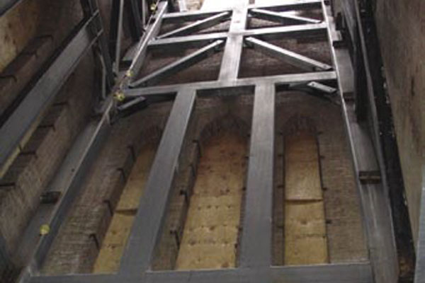
Space was at a premium within the existing tower. Steel was chosen for the new structure because it provided the least intrusive and most easily constructed system. The new structure was designed to fit within the brick masonry walls of the existing west tower and to be supported by a new foundation at the base.
The new foundation design was also integrated with the existing foundation. This foundation consisted of a 35’ × 35’, 4’-thick mat designed to support the new tower and to supplement the existing strip footings beneath the existing tower walls.
The tower’s design accounted for large overturning forces due to the relatively small 16’ × 16’ footprint. The stiffness of the tower was of paramount importance to limit differential movement between the new and existing towers.
Load Conditions
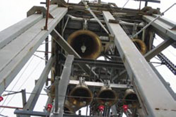
The tower had to support several unique loads, including a heavy brick and cast stone façade backed up by concrete masonry unit blocks. In addition to these loads, the tower also had to support a 50,000 lb, 49-bell carillon and a 14,000 lb pre-manufactured steeple.
The lateral loads, however, ultimately controlled the design. Lateral wind loading was a crucial design concern because of the tower’s slender nature. In addition to the wind loads applied to the structure, lateral forces included the reaction from the bell carillon, which contained four large, swinging bells. These bells weigh almost 18,000 lb and exert approximately 15,000 lb of lateral force when swinging.
The steel structure also had to respond to the architecture of both the existing and new towers. A complex bracing configuration that involved both diagonal bracing and rigid frame action was required. Corner HSS columns were filled up to 64’ with 7,000 psi concrete after erection to increase load capacity and, more importantly, to increase stiffness at the column bases where lateral bracing was prohibited.
Large openings were made in the new tower’s façade at elevations of 94’ to 126’ so that the bell carillon is visible from the ground. The columns at this area are composed of 14”-square HSS corner columns. These columns have an HSS 16 × 8 stitch-welded to two sides and an HSS 8 × 6 stitch-welded to each 16 × 8. This modified built-up section provides unobstructed views of the bells and maintains the stiffness of the tower. Overall, the lateral deflection of the tower was limited to less than 1” at the top of the existing masonry and to 3” overall.

This RISA-3D model shows the steel framing inside the masonry and cast stone façade.
Prefabricated Elements
Two sides of the tower were shop-fabricated and shipped to the job site pre-assembled to limit the amount of field erection and to expedite the erection of the steel frame. These frames had three splice points along each column because trucking requirements limited the size that could be shipped.
The largest prefabricated section was approximately 16’ wide, almost 43’ tall, and weighed over 12 tons. This section was partially assembled off site and erected during off-peak hours. Much of the steel structure was erected in the middle of the night, when traffic lanes could be closed for crane access. The remaining two sides were in-filled with field-erected pieces once each section of the preassembled frames was erected.
All primary structural steel had to be fireproofed to an elevation of 85’ to comply with the applicable building code. Structural steel below this elevation was architecturally exposed, and intumescent paint was specified to ensure adequate fire resistance while providing a smooth, clean finish.
Stair Design
The steel framing was pushed as close as possible to the exterior walls of the original tower to gain interior space for stairs and amenities. At its closest point, the new tower structure was within 3” of the existing tower walls.
The clavier (the instrument by which the bell carillon is played) had to be positioned as close to the bells as possible. The bell carillon is 94’ above the ground, and the clavier is just below the bell level, at an elevation of 85’. A unique stair was necessary for access to the instrument. The entire stair is exposed and visible from the base of the tower. It is composed of a single center tube with bent steel plate treads and risers that cantilever to each side of the center stringer. This design creates a thin, light stair profile that minimally intrudes upon the tower’s open interior.
Access to the sanctuary’s choir loft is also provided through the tower. The lower section of the choir loft stair was designed to have a more architecturally elaborate configuration. The stair is a self-supporting spiral with no intermediate supports. It is only connected at the choir loft landing and at the ground, creating a 25’-tall spring. This stair was designed with a similar structure to the upper stair and consists of a center stringer with bent steel plate forming treads and risers.
Bending a steel tube in all three axes to form a spiral, while keeping the top side flat to accept the tread and riser plate, was complicated. Therefore, the stringer was designed as a built-up box beam from steel plate. The plates could be cut, bent, and manipulated to provide the correct shape and then could be welded together to form a stringer that satisfied the design requirements. The stair required careful, painstaking fabrication and erection—especially because it would be architecturally exposed and imperfections would be visible.
Construction
The contractor joined the design team during the design process to coordinate installation of the brick, cast stone, and other masonry on the tower. The contractor used a moving scaffold system that covered each face of the tower. This was not a problem on two faces because the masts of moving scaffolds could be easily supported on the ground. However, these scaffold masts were positioned over the existing building’s roof on the two remaining sides.
Platforms, required to support a 21,000 lb scaffold load, were placed on the east and north faces of the tower. These support platforms remained in place for the duration of the tower construction and were removed once the scaffold systems were taken down. Each platform cantilevered approximately 10’ from the new tower structure at an elevation just above the level of the existing tower. The cantilevered platform support beams were placed in window openings to avoid interruption to construction of the tower façade while the scaffolds were in place.
Installing the carillon’s large bells, the largest being almost 6’ in diameter, without structural interference was a challenge. A hoist beam capable of handling a 10,000 lb load was designed and installed at the top level of the steel structure. This beam was used to hoist the bells from outside the tower to an opening in the floor above the bell chamber. The bells were then lowered to a point at which they could be installed on the bell frame.
A ceremonial concert was played on the tower’s new bell as the bishop of the Diocese of Dallas dedicated the new tower on September 11, 2005.
Stephen H. Lucy is a principal of Jaster-Quintanilla Dallas, LLP. Todd Nicholson is a graduate engineer with Jaster-Quintanilla Dallas, LLP.
All photography and graphics for this article are courtesy of Jaster-Quintanilla Dallas, LLP/Andres Construction Services.

